This section explains how to capture a process flow in Requirement Management and is the third step in capturing requirements.
Process Capture comprises Tools, Process Map, Requirements, and Appendices.
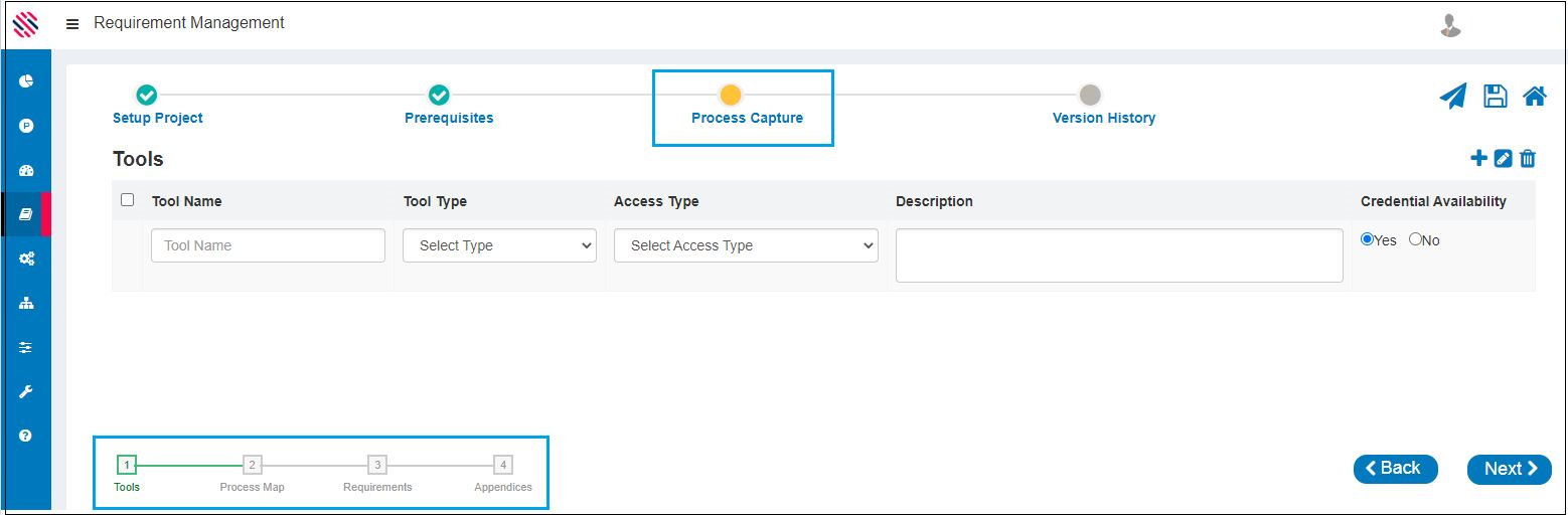
Figure 1
Tools
Fill in details under the Tools section in the following manner:
Enter the Tool Name. Select the Tool Type and Access Type from the dropdowns. Provide a Description and Click yes or no in the Credential Availability field. (Credential for the various potential applications or URLs that will be used in the proposed automation) Add it as a row. Click on the Next button.
Note: Checking the box adjacent to the row will allow one to select the row. Checking the box next to the Tool Name field will select all rows.
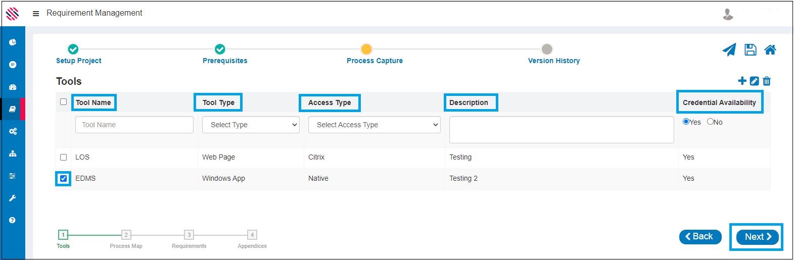
Figure 2
Process Map
One can Browse and upload images that are to be depicted in the As Is and To- Be Process Maps. Browse and select another image to replace the existing image
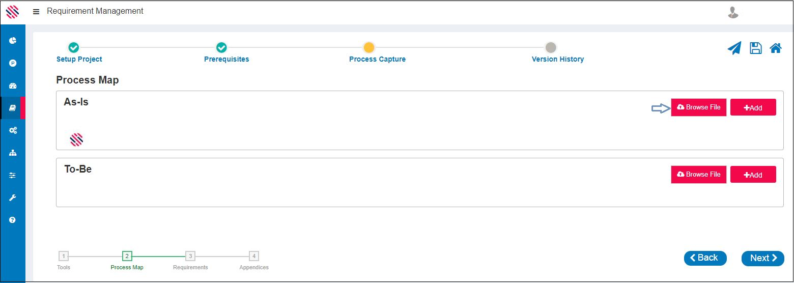
Figure 3
One has an option to use the draw charts for a pictorial representation of the Process Flow that comprise the AS-IS and TO-BE processes. Click on the Add button. Refer Figure 3.
Use the various shapes, placement options found on the left side. Click on the shape to apply color. Click on Ok after you have completed.
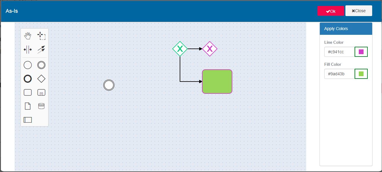
Figure 3.1
The edit option will be enabled once you have created any image.
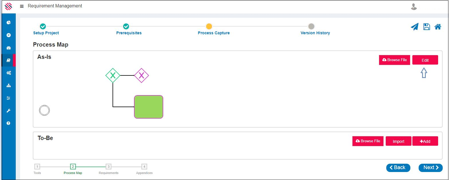
Figure 3.2
Use the Import option to copy workflows.
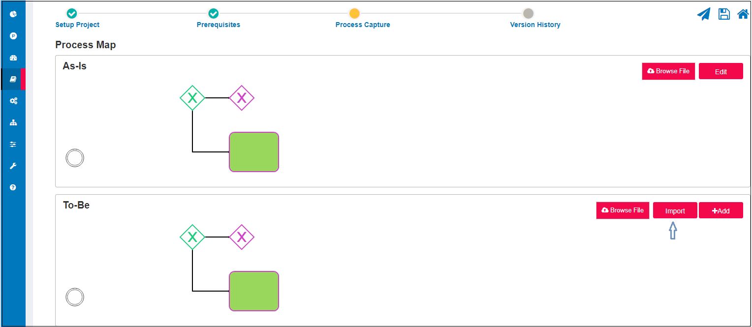
Figure 3.3
Thus, one can use both images and drawings to depict the process flow.
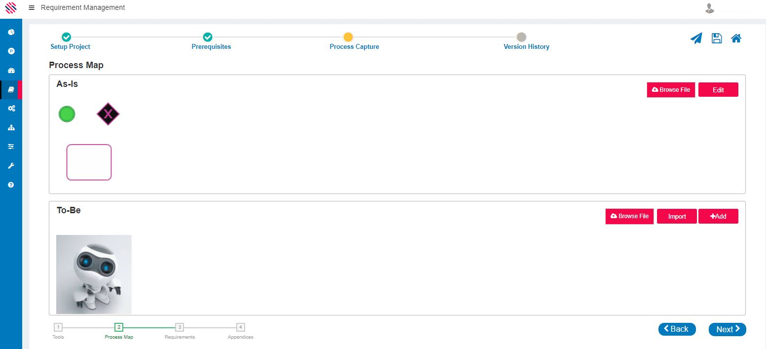
Figure 3.4
It is mandatory to present the As Is and To Be Process flows as diagrams or pictorial representations.
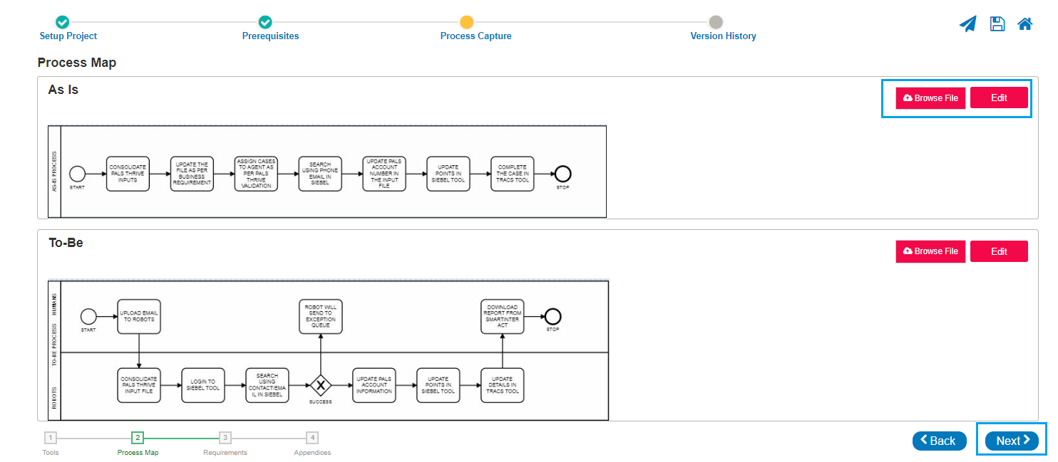
Figure 3.5
Requirements
Fill Requirement Steps
Click on the + icon to enable the "Fill Requirement Steps" screen as displayed in figure 5.
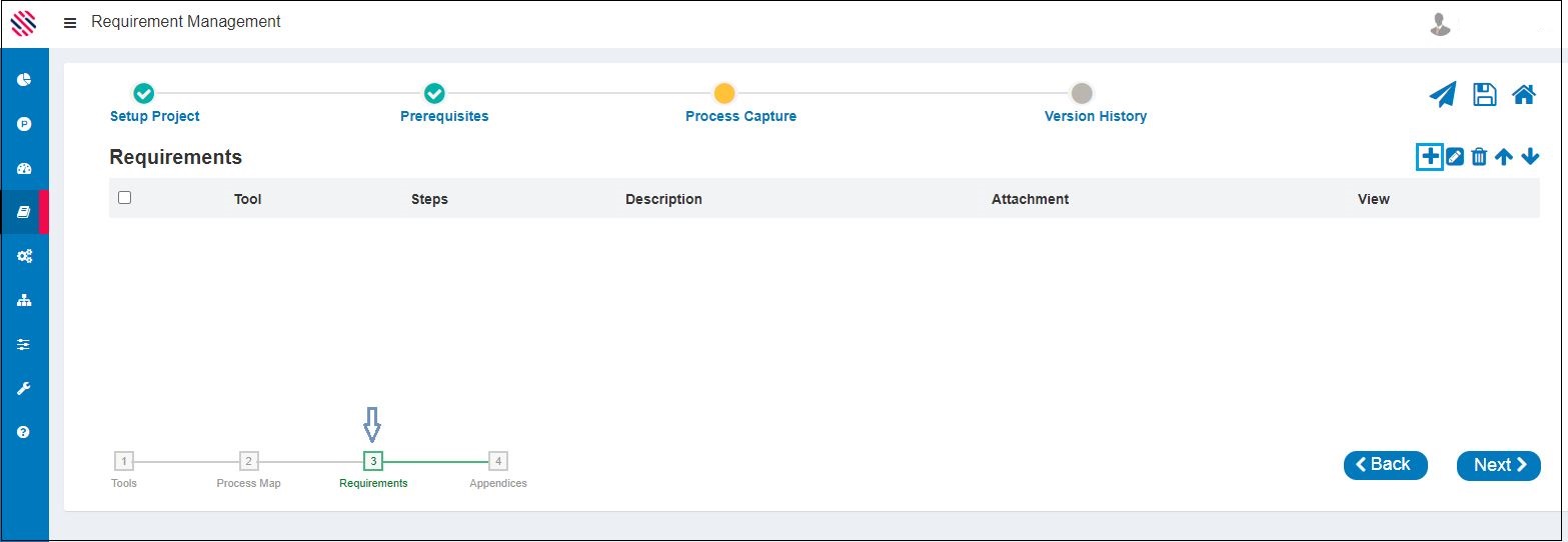
Figure 4
Proceed to select the Tool from the drop-down. Enter the name and a comprehensive description of the Requirement in the steps and Description fields, respectively. Browse and Upload the necessary file, if required. Add File Button is used to upload more files. A maximum of three files can be uploaded at a time. Once all information is provided, Save. The requirement will be created successfully.
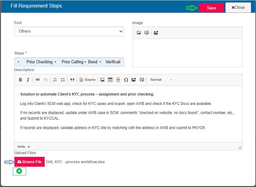
Figure 5
Thus, the requirement will be created just as the user has captured it. Requirement Details can be viewed using the eye icon.
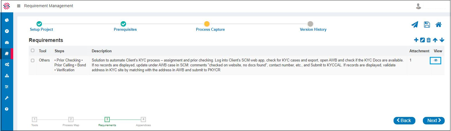
Figure 6
The created requirement along with details, down to the attachment will be displayed.
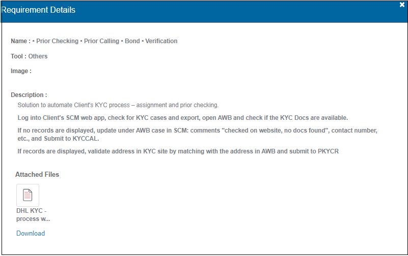
Figure 7

Figure 8
Note: The  symbol is used for adding additional rows. The Eraser Icon is used to edit. The bin icon is used to delete. The upward facing arrow
 will allow a row to go one row up and the
 downward facing arrow will allow the row to move one row down.
Click on Next to Save the changes after every entry or one may lose the changes or even the entire record that was created.
More than one requirement users or Requirement approvers are allowed to work on the same requirement.
Image Properties.
Using the properties available here, one can Insert, Upload and Edit images.
Insert an Image

Edit an Image

Upload an Image

Insert an Image
Insert an image by typing in the copied address of the image under the URL header. Customize according to requirements with the given options. Preview before clicking on the Ok button.
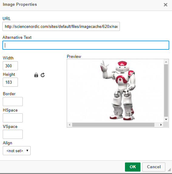
Figure 9
Edit an Image
One can use the highlight and crop options from the drop-down to make the image more attractive and enhance the same by using assorted colors as well. Save before closing.
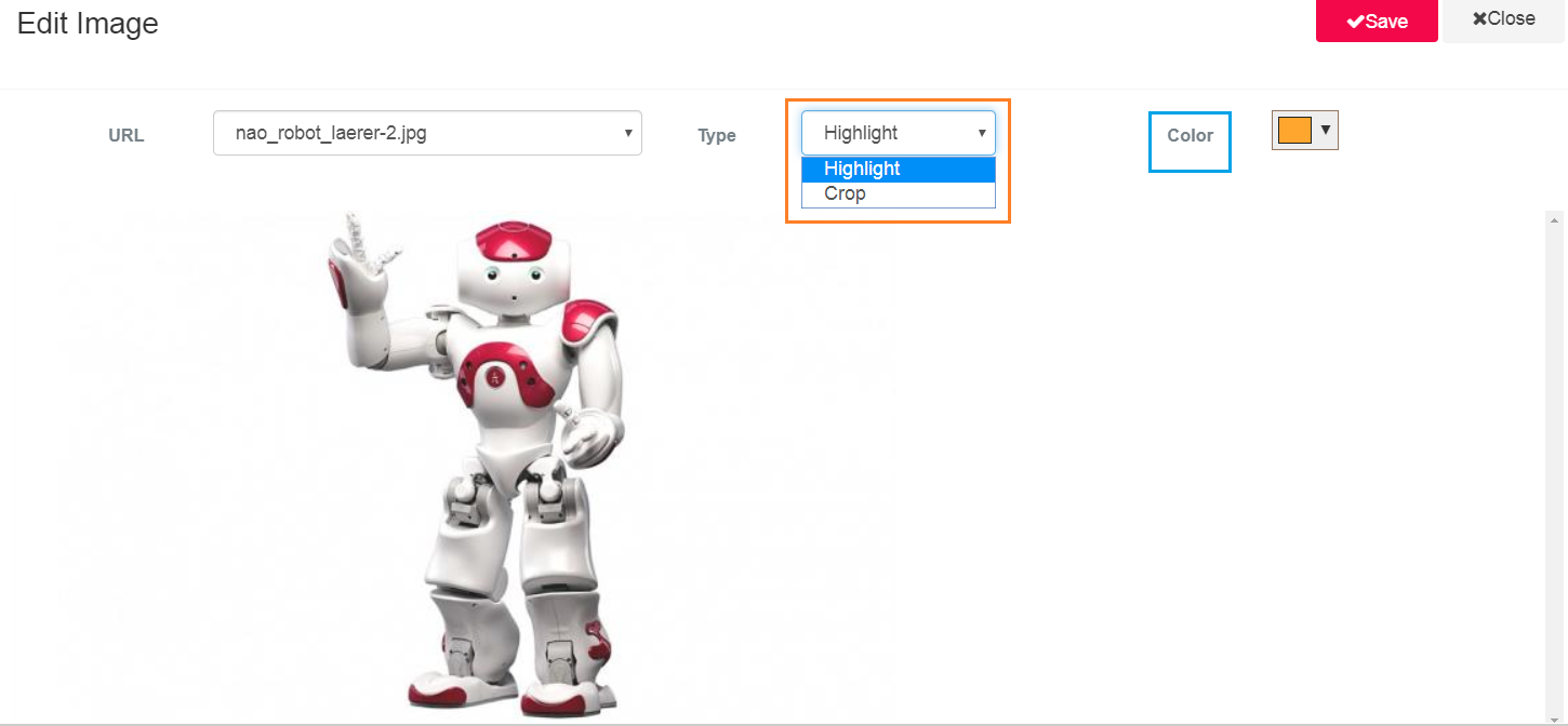
Figure 9.1
Upload an Image
One can upload images as per requirements.
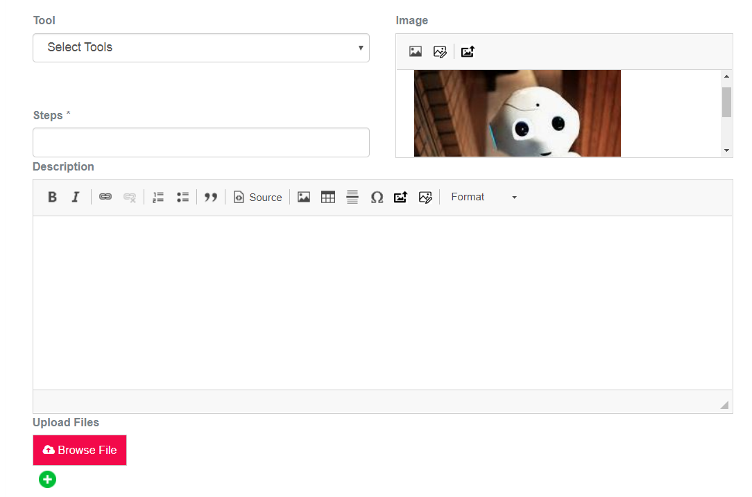
Figure 9.2
Appendices
Appendices section is to be filled with list of Acronyms and Glossary of Terms. Enter the same in the given text boxes and click on the plus icons. Click on the Next button to save.
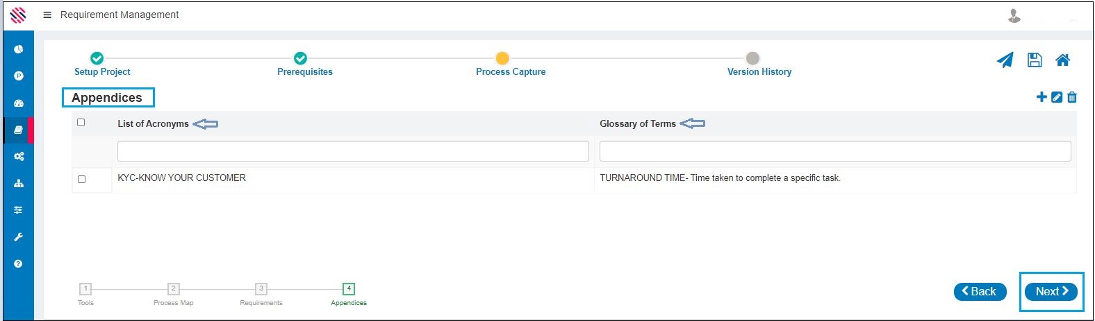
Figure 10